Trackball
C++, Arduino, Electronics, DIY, FreeCAD
2023
Everyone who works with computers will reach the stage of wanting to improve their peripheral ergonomy sooner or later. We use them for hours without end and sometimes feel a tingling on the wrist at the end of the day. Although, luckily, I have not been suffering from RSI, I still decided to take the lesson from other less fortunate people and begin to transition to a more ergonmic layout and setup before it was too late. This is how it began. I got myself the components for a Redox Keyboard and assembled it, and although everything felt more comfortable and ergonomic, moving the cursor through the mouse was still straining. So I did what any reasonable person would and started researching for solutions to my problem.

A small snapshot of the assembly of my Redox keyboard.
After some time researching, I randomly found on github a tiny DIY trackball device. For sure it would be cheaper to buy a trackball or another more ergonomic pointing device or even getting the components and copy that beautifully made DIY peripheral, but the possibility of making my own unique device excited me as a wonderful summer project.
Challenges
- Design the circuit.
- Not having access to a pre-made PCB.
- Selection of right components.
- Designing my own device using 3D modelling tool and printing it.
3D Modelling and prototype
I had dabbled on FreeCAD very lightly and this was the perfect chance to go back to it and learn a bit more on how to properly design some basic shapes. Having no PCB also made the build a bit more unconventional and large. The prototype boards sticking from the side of the case reminded me of the famous boxer engine from a certain motorcycle make…

Early design for the top of the device. Created in FreeCAD.

The first design of the trackball version 1 soldering the sensor and other components.

The last design of the trackball version 1 plus setup. Made the body to protect the circuit, fit a Pro Micro board and have a small connector for two keys that can be used as click inputs.
I was quite happy with the result and it surely complements the look of my setup. The code was pretty straightforward as there were libraries that required a few tweaks. From designing the board, to the body and getting all the parts together after some trial and error, I can proudly say that I have been using it for months now and haven’t had any problem with it.
2024 Update
New year, new challenge: Add buttons to my prototype and try out a BTU (ball transfer unit) support for the ball instead of using normal bearings. Plus, I would like to reduce the size of the sensor board by getting a proper breakout board for it instead of manually doing one myself. With that in mind, I got to work on modelling the new body. I like modularity and being able to switch components as easily as possible, so I wanted the buttons, switches and encoders to be very accessible with minimal effort. This is the model I came up with:
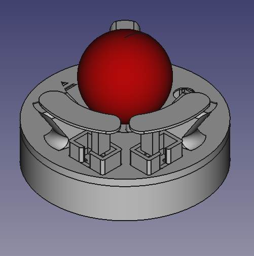

FreeCAD render of the model created.
Two removable buttons with kailh switches, an encoder on the side for auto-scrolling and an extra button and a screwed top. I also made the arrow pointing forward to ressemble an “A”. This will be the logotype of the model. I called it “Albatros” because the design reminded me of a biplane. So why not give it the name of an iconic WW1 biplane?
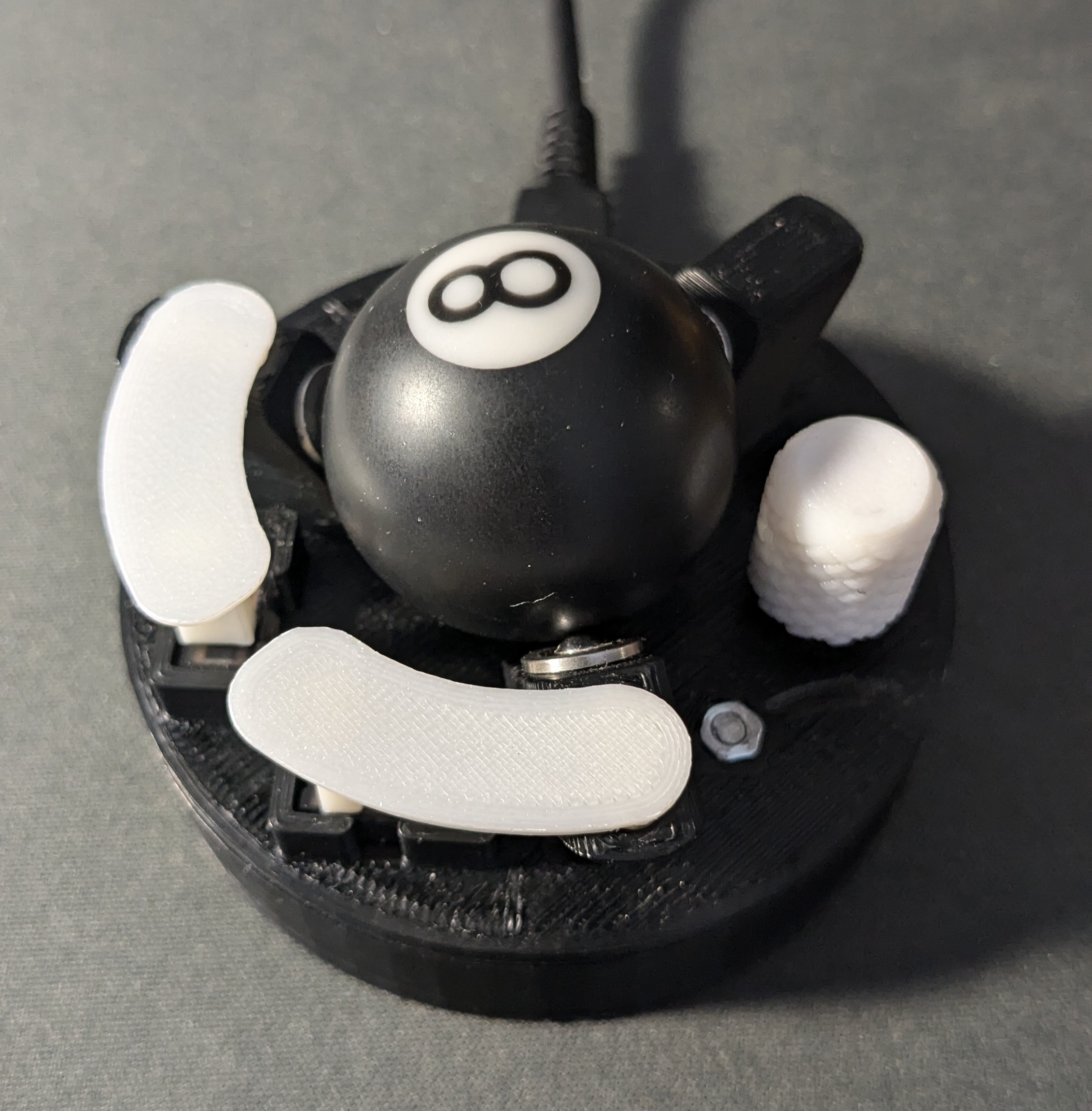

The printed "Albatros".

A view of the updated setup.
Once again, designing and creating this new prototype was a wonderful experience. I was able to try out new components, learn about interrupt pins and functions for arduino and how encoders work.

A comparison picture between version 1 and 2.